


The Porsche Type-915 Transmission - Part VII
(All of these parts are available to purchase through Red Line Service in Los Angeles, Ca.. For more information, call (310) 280-0700, or email us at ten.ecivresenilder|ofni#ten.ecivresenilder|ofni)
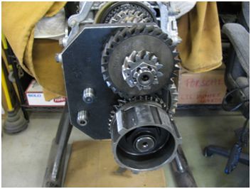
This section of the Tutorial is very picture-dependent. Let’s start by cleaning thoroughly the various parts of the 1/2 shift fork and shaft, same for the 3/4 fork and shaft, and the remaining detent components. Pick up the 1/2 shift fork shaft, coat its detent end with white Lithium grease…
…and slide it into its opening in the differential housing.
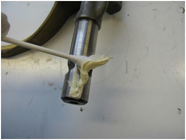
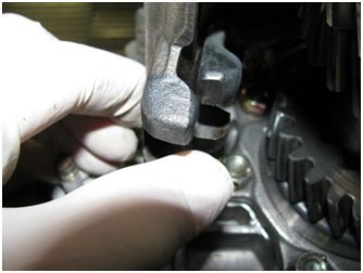
Locate a side-load detent…
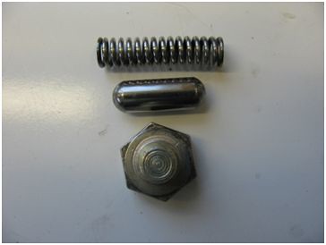
…insert the detent, with a little dab of grease…
…followed by the spring…
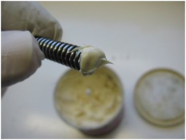
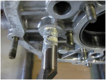
…and the screw plug.
Don’t worry; the above picture shows that the plug must be pushed firmly in order to compress the detent spring, and then you have to carefully align the plug with the threads to start it into the opening.
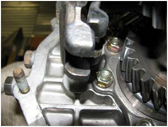
NOTE: If your screw-plugs had sealing washers fitted to them during disassembly, use the two new washers in your gasket set. If your plugs had no washers put the plugs in without them.
Torque the plug to 12 lb/ft; this is one of those rare exceptions when a hardware item with 10mm threads has a very low installation torque, but design dictates the spec.
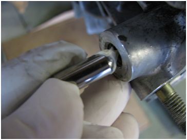
Put a very light coat of white grease on the end of the 1/2 shift fork shaft (this will ease pinion shaft installation), put the 1/2 fork in place on its slider, and simultaneously engage the fork on its shaft while gently pushing the head of the pinion into the bearing race in the diff housing. After the pinion shaft is in the housing by about an inch, stop. You won’t believe this, let go of it. Go ahead, dare to defy gravity.

Pretty cool, huh?
TEST: What’s wrong with the above picture? The clue can be seen in the below picture…

TEST ANSWER: I forgot to install the pinion depth shims, while worrying if my camera had enough battery left for this set of pictures. D’oh!
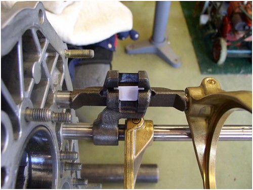
Smear a little grease on the detent end of the 3/4 shift fork shaft, and place the fork/shaft in position on the main shaft slider.
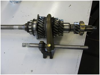
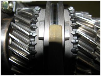
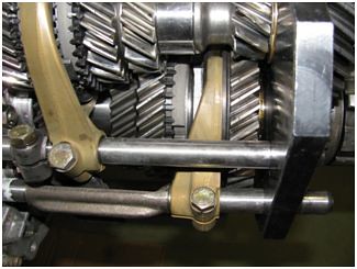
Slide the clutch end of the main shaft into the diff housing, and forward until you can lower the black fork into position on the gear side of the 1/2 fork shaft. At this point line up the two gears of 4th speed, and, together, start to push the main shaft and pinion shaft home.

There are times when the shafts, with little effort, will slide into place, but usually they will resist. Patience is your friend. You will probably have to wiggle the shafts, re-align them, push them, swear at them, struggle to keep the flat sides of the two clamping plates together, try not to cut off your finger tips, and, finally, they will get where they need to be.
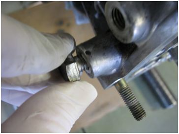
Place a split-lock washer on each stud, followed by a regular, 8mm nut. Don’t tighten them yet. Be aware that your washers must be of a small enough O.D. to fit into their recessed areas on the clamping plates.
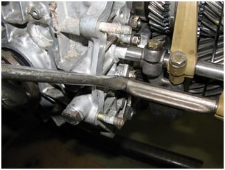
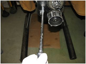
Now we’re going to do something that you won’t find in the books. Install your P 260A tool onto the main and pinion shafts. I discovered many years ago that by using the P 260A during clamping plate tightening, the pinion and main shafts turn smoother and easier than if they’re tightened without the holder in place.

Tighten the ten nuts in a random crossing pattern. Skip around from one to another; snug them a little at a time until they are all tight. Torque is 17 lb/ft, but you can’t access all of the nuts with a socket. The best way to do this is to torque the lower nuts on the pinion shaft plate, then practice with a good box end wrench until you can “feel” how tight the already-torqued nuts are. Final tighten the nuts that can’t be accessed with a typical torque wrench. If you have invested heavily in the Stahwille torque wrench for-hard-places-system; kudos to you!
NOTE: During disassembly you might have noticed that the clamping plate lock washers were black. This indicates a small O.D. washer (mentioned above), and if you have all ten of them, and they look good (they should not be spread apart at the split), re-use them.
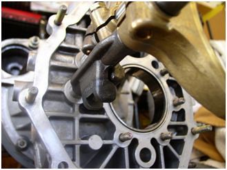
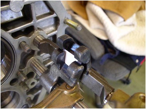
Set your 3/4 shift fork/slider mid way between 3rd and 4th gear, and install your remaining detent, spring and screw plug. Install your 8mm bolt, with a wavy-type lock washer, into your 1/2 shift fork and snug it down; it doesn’t have to be tight.
In order to adjust shift forks, the main shaft and pinion shaft nuts must be tightened to their actual torque spec. This will draw all the components of the gear stack together as they will be in the finished transmission. To do this we must install 5th gear and the other parts shown in the below picture.
Re-use the old pinion shaft collared nut, engage 4th gear and install your P 37A. Torque the nuts to 181 lb/ft (P/S) and 116 lb/ft (M/S). I have agonized over this part of the Tutorial, and I’ve decided to use a teaching method that I developed a while ago to help a fellow Porsche enthusiast through the process. I feel that the factory manual, wonderful in almost every application, hung us out to dry on shift fork adjustment, so I have expanded the level of instruction to attempt to achieve a perfect result. What you will see in the next series of photos are the shift forks, without the gears/shafts.
We’ll start with two pictures that will give you a general idea of where the forks will be post adjustment. The first photo, SF-1…
SF-1
…is a view that you can see with the shafts and gears installed. The next picture, SF-2, is a view that can’t be seen with the gear stack in place, but serves to illustrate the approximate final position of the forks.

SF-2
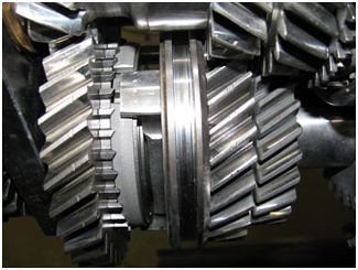
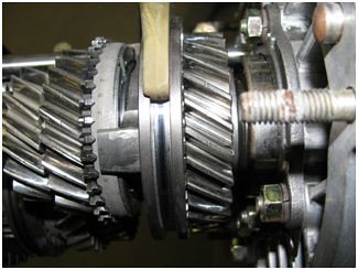
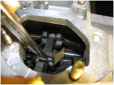
Picture SF-3 has the transmission turned 180 degrees to simulate viewing the fork position from under the transmission. Note that each shaft has a brass, “gold” fork, and a “black” fork. The black forks are what we’re concerned with now. You can see, in SF-3…
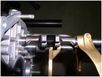
SF-3
…that the fork openings are almost lined up, and that the forks themselves do not, at any point, touch each other.
NOTE: The desired result of shift fork adjustment is to make the internal parts move the proper amount, and in concert with, the external shift linkage. Remember, shift forks don’t operate in a vacuum; they are part of a system that start’s with the driver’s hand.
I begin the adjustment process by setting the black fork on the 1/2 shift fork shaft, while at the same time setting the 1/2 brass fork/slider in the middle of the area between 1st and 2nd gears. Have the fork bolt snug enough to allow the shaft to turn inside the 1/2 fork, but hold a set position. We start by moving the black fork counter clockwise, push it toward the gear stack, as shown in SF-4…
SF-4
…until it stops, then I’ll rotate it clockwise; and pull it away from the gear stack, as shown in SF-5…
SF-5
…that will illustrate how far the fork can move between its two stops. Now, to adjust the fork, go all the way back to the opposite stop shown in SF-4, and then move the fork away from the gear stack until its inner, flat, un-machined surface reaches almost vertical, as seen in SF-6…
SF-6
“Vertical” is seen by comparing the fork to the vertical strengthening rib, cast in the diff housing, which extends from the outer sealing surface near the bottom of the housing, up to the orifice for the 1/2 shift fork shaft. That rib is seen clearly in SF-2.
This adjustment is tricky, because Porsche states “almost vertical,” but the vast majority of 915s that I’ve done require vertical – but NEVER past vertical. I have concluded that a very fine line exists between “almost vertical,” and “vertical.”
NOTE: Before attempting the above adjustment, position the transmission so that the vertical rib is vertical, and you’re able to focus on only it and the 1/2 black fork’s inner surface. When that flat, un-machined surface is in alignment with the aluminum rib the fork can be considered vertical. If you find yourself going a little cross-eyed doing this procedure; go for a short walk.
Once the black fork is where you need it to be (it has no fore-aft adjustment), position the 1/2 brass fork so that its shift slider is exactly in the middle of the 1st and 2nd gear synchro rings. Without changing the black fork’s adjustment, snug down the shift fork’s bolt so that nothing can move. I use my thumb to apply downward pressure against the brass fork while I tighten the bolt. Torque the bolt to 18 lb/ft.
Move to the 3/4 shift fork/slider, position the slider exactly between those two synchro rings as seen in SF-7…
SF-7
…and torque that fork bolt to 18 lb/ft.
Use a screwdriver and test-shift the transmission. SF-8 shows how to apply pressure to engage 1st gear…
SF-8
…and it looks like SF-8a.
SF-8a
In picture SF-9 we’ll put the transmission in 2nd gear…

SF-9
…and it’ll look like SF-9a.
SF-9a
Picture SF-10 shows how to engage 3rd speed…

SF-10
…and it’ll look like SF-10a.

SF-10a
Picture SF-11 shows how to engage 4th speed…
SF-11
…and it’ll look like SF-11a.
SF-11a
NOTE: We’ll deal with 5th and reverse during final transmission assembly.
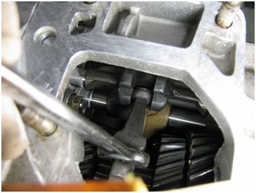
OK, now it’s time to take care of the final adjustment in this part of the Tutorial. 2mm-3mm of clearance, sounds so easy, doesn’t it? I’m going to post picture number SF-3 again now…

SF-3
Remember, in this picture the transmission is upside down (the pinion shaft is above the main shaft). The relationship of the opening in each black fork must be so that they are centered to each other. In other words, the outboard edges of each opening must be as closely aligned as possible so that no “step” exists. Some forks are manufactured a tiny bit different than others, if the edges don’t align perfectly minimize any existing step, such as the one pictured in SF-3, by splitting the difference. Don’t make yourself crazy with this; just try to make any existing step as small as possible. Two tiny steps, one on each side, are better than one larger step. To “cure” the pictured step I loosened and moved the adjustable black fork on the 3/4 shaft a tiny bit to our left, as seen in the above picture.
2mm – 3mm clearance; for that, and an end to this madness, we must refer to pictures SF-12 and SF-13.
SF-12
SF-13
Pictures SF-3, SF-12, and SF-13 have been left over-sized intentionally. The white paper that you can see is the place where the 2mm – 3mm of clearance must exist. This step is the one that converts a poor to fair shifting 915 into a great-shifting 915. And it should be done with the transmission upside down, and the work area well lit.
With the fork bolt tight enough so that the adjustment can’t change, use a finger and thumb to gently push the two black forks toward each other. At the stop for that motion there should be 2mm of clearance. Move the forks apart to the opposite stop, and there should be about 3mm of clearance. The adjusted clearance can be seen clearly in SF-3 by looking at the horizontal gap in the dark, shaded area of the base of the fork openings. If your adjustment is outside of the allowed range, loosen the bolt for the small, black fork on the 3/4 shift fork rod and adjust as necessary. Be aware that if your fork opening alignment was already set, and correct, you must not change that adjustment while setting clearance. When you’ve got both adjustments correct; torque the bolt to 18 lb/ft.
This is when I double-check all of my settings. I turn the trans so that it’s up side up, test shift, as illustrated earlier, 1st through 4th speeds, then re-check both sliders to be sure that they are exactly centered between their respective pairs of synchro rings. When I’m satisfied, I re-torque all three fork bolts to 18 lb/ft, turn the transmission upside down, and re-check the alignment and clearance of the two black forks.
I, once again, rotate the transmission, torque the three bolts again, and call it done. Kinda. I hate to admit this, but I repaired a 915 about 30-years ago that didn’t go so well. Remember the “rotate the 1/2 shaft black fork counter clockwise, then back to vertical, procedure?” Well, I didn’t quite understand what “almost vertical” meant, and didn’t get that adjustment quite right. I sealed and final installed the center housing, 5th speed and reverse, and the nose cover. I rotated the trans to install the shift fork plate, rotated the shift rod to make sure that its finger was secure inside the black forks, and discovered that the finger did not have sufficient clearance to engage the 1/2 shaft’s black fork. I had not rotated that fork far enough toward “almost vertical,” and the finger hit the inside of the fork opening.
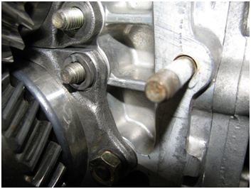
So now we double-check our work before final assembly. First, remove 5th gear and special tool P 260A. Slide the center housing, complete with the shift rod, into position over the gear stack, and secure it with a couple of nuts across from each other.

Do the same with the nose cover. Do not use any seals, gaskets or sealant.

Turn over the transmission, engage the black forks with the shift rod’s finger, and move the finger back and forth to make sure it fully engages both forks without hitting anywhere.
Only five extra minutes of work, to save a lot of grief. Can you imagine installing and filling the transmission, starting the car, and then discover that it won’t shift into 1st or 2nd? Aaaaaarrrgh! OK, remove those covers and let’s get ready to assemble our subject.
Now we’re done, until Part 8, that is. Keep the shiny side up!


